Mux multiplexer cascading types circuit multiplexing application logic electricalfundablog fig Mux multiplexer schematic inputs structure diagram considering Verilog code for 2:1 multiplexer (mux)
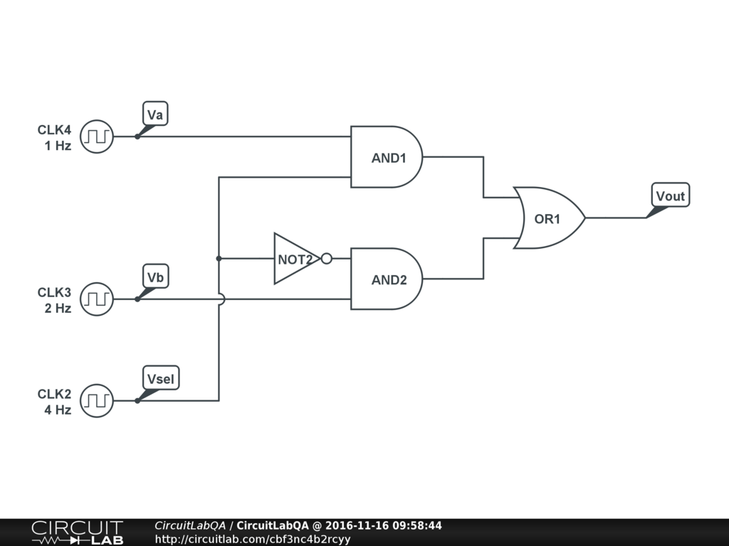
4 x 1 mux using logic gates - Electronics Q&A - CircuitLab
Mux cmos schematic logic diagram Multiplexer gate consists clearly Mux using gate xor draw asic vlsi chip system
Mux part circuit hdl
A multiplexer schematic structure, b truth table of the mux based onLayout of the mux using the proposed 2-input xor gate. Mux multiplexer cascading multiplexing electricalfundablogMultiplexer in digital electronics, block diagram, designing, and logic.
8x1 mux uniqueMux using diagram block only 16 four logic digital electronics 2x1 mux : vlsi n edaVhdl 4 to 1 mux (multiplexer).

Multiplexer (mux)
2x1 mux multiplexer logic diagram schematic symbol vlsi using gates inverter eda input figureMux multiplexer vhdl logic using gates code use Make an or gate using a muxMux logic gates using implementation courses.
Mux multiplexer logic diagram using tableMux circuit logic gates using circuitlab input electronics make once working questions need two Transmission gate based 4:1 muxMux 8x1 multiplexer schematic using input 2x1 muxes vlsi symbol structure figure universe eda label.

Mux multiplexer cascading logic multiplexing bits
Multiplexer (mux)Mux implementation using logic gates Mux multiplexer input bits cascading multiplexingMux input xor.
8:1 mux : vlsi n edaMultiplexer (mux) Layout of the mux using the proposed 2-input xor gate.Multiplexer mux truth gates nand inputs boolean multiplexing combination fortunately elcho.

Mux multiplexer 8x1 diagram mainetreasurechest unique source
Multiplexer (mux)Asic-system on chip-vlsi design: draw xor gate using mux. Modern circuit design — cosc2325 fall2018 documentation8 to 1 mux.
Mux using gates logic input circuit circuitlab electronics chain together questions them makeDigital logic Mux multiplexer verilog 2x1 code technobyteMux using gate 2to1 make figure copy.
Schematic of 2:1 mux using cmos logic in dsch2
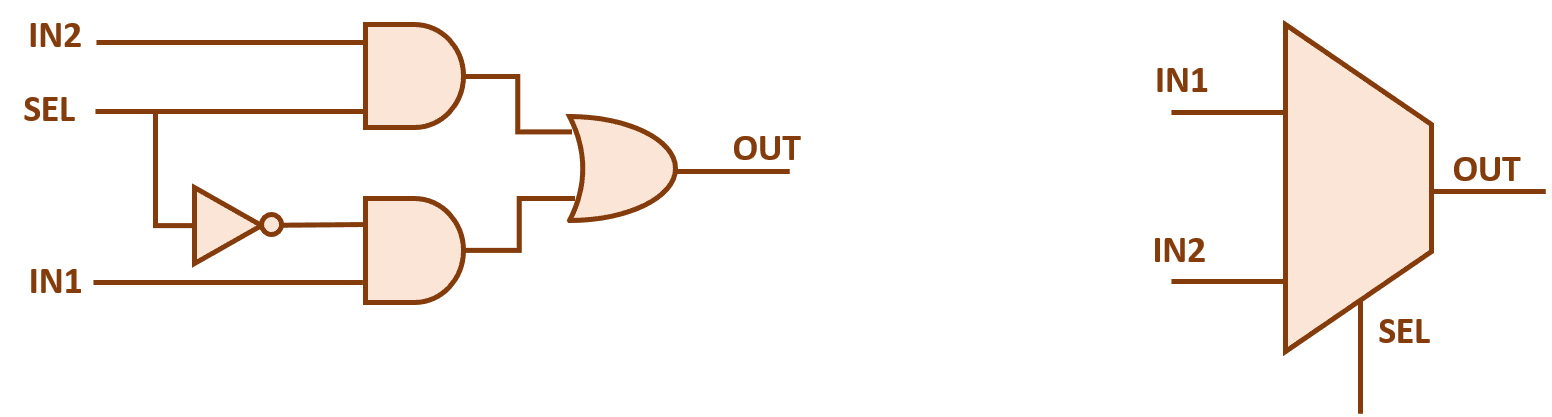
Mux transmission4 x 1 mux using logic gates Gate-based 2-to-1 mux.Nand2tetris part 1: boolean algebra and logic gates.
4 x 1 mux using logic gatesXor mux gate input proposed .


Gate-based 2-to-1 MUX. | Download Scientific Diagram

Layout of the MUX using the proposed 2-input XOR gate. | Download

8:1 mux : VLSI n EDA

Multiplexer in Digital Electronics, Block Diagram, Designing, and Logic

a Multiplexer schematic structure, b truth table of the mux based on

4 x 1 mux using logic gates - Electronics Q&A - CircuitLab
4 x 1 mux using logic gates - Electronics Q&A - CircuitLab
